 |
|
|
|
|
|
|
|
|
|
|
|
|
|
|
|
|
|
|
|
|
|
|
|
|
|
|
|
|
VUTRAX Specialised Modules
Silkscreen Renumber
Provides logical numbering of symbols or devices on a schematic or on a PCB. You can choose direction, separately on each side as appropriate, to optimise production, testing and servicing.
Silk Replace
Manipulates footprint component outlines and pad styles. Beneficial when applying resistive inks and bonded ICs to thick film hybrids.
Statistics
For quantitative analysis of the design for copper areas, track segments and width analysis, pad sizes, drilled and finished hole size, board occupancy and dimensions.
Mass Edit
A powerful graphics editor allowing global changes and/or deletions of point types, layers, track widths, pad sizes and named structures.
Technical/Mechanical Drawing
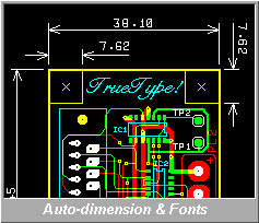 A substantial technical drawing capability is available for
use with PCB designs or for any other purpose. Our customers
use these features for designing their front panels, chassis,
dimensioning board cut outs etc. Features include
A substantial technical drawing capability is available for
use with PCB designs or for any other purpose. Our customers
use these features for designing their front panels, chassis,
dimensioning board cut outs etc. Features include
- Numerous styles of auto-dimensioning including angles.
- Drawing curves and spirals.
- Radiusing corners (filleting).
- Area Fill, Hatch and Cross Hatch.
- Numerous Dotted and Dashed line styles.
- Scaled drawings (enlarged or reduced)
- Automatic locking of drawing to isometric or similar axes.
- Use of any Microsoft Windows TrueType Font with correct reproduction even on photoplotters.
CAM Analysis
PCB assembly and test output, both graphically and by numeric coordinates from a datum. Facilities include GLUESPOTS for Surface Mount on and Pick & Place machines, and TESTPOINT analysis for bareboard or functional testing using ATE.
3D Visualisation
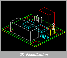 This feature displays Isometric and/or 3rd Angle projections
of the board, including component heights. Height limits can be
set (varying over the board) to apply limitations imposed by
the boards environment. The isometric output is particularly
useful for annotation to produce documentation, such as showing
the position of switches and connectors.
This feature displays Isometric and/or 3rd Angle projections
of the board, including component heights. Height limits can be
set (varying over the board) to apply limitations imposed by
the boards environment. The isometric output is particularly
useful for annotation to produce documentation, such as showing
the position of switches and connectors.