

BULLETIN
Technical Support and the Latest Information for VUTRAX Users
|
Issue Number 28 |
April 1998 |
- PRODUCT STATUS -
Associated with this document is a Technical Summary, reporting the current Product Status of each program.
- VERSION 12.0 -
Installation
All customers are delivered identical sets of master software, supplied on CDROM, a set of about 7 floppies or downloaded from this Web site.
In addition to the above software you will be supplied with a Configuration Disk which contains 1 or more software configuration files (.CF?) that determine what is installed on your system. For software additions this file can be e-mailed to you to provide an 'instant' upgrade.
Some customers with 3rd Party interfaces will also receive an Interface Disk, which needs to be installed separately.
All media can be copied, networked, or whatever is required to make installation easier, but editing the configuration files will render them invalid.
During installation you can choose on which drive/directory you wish to install Vutrax (defaults to \VUTRAX). Options are also available to exclude installation of items such as Examples, Help, Tutorial, and Standard Library files.
Database Change
The major enhancements achieved in Vutrax 12.0 are primarily concerned with functionality and were impractical without a database change, and/or with 16 bit (Windows 3.1/3.11) operating systems. Thus version 12.0 is only available on 32 bit operating systems (Windows 95, 98, NT 3.51, 4.0 and 5.0).
In order to handle the extended fields the system has been optimised so that the binary files are usually smaller than for similar data in VUTRAX 11. All your data and libraries are forward compatible - VUTRAX-12 can still read and edit files written in the 1980's!
A graphics converter from VUTRAX 12 to 11 format (with necessary approximations) will be freely available to all VUTRAX users both as part of VUTRAX-12 (32 bit version) and from the Web site a 16 bit version for Windows 3.1 onwards.
Additional Directory
The VUTRAX 12.0 directory structure is basically the same as version 11.7, except for the addition of \VUTRAX\TEMP. This directory is used for the bulk of temporary work files regardless of the current directory for the project. These files are removed during start-up of Vutrax in a particular windows session. Projects and File Management will be discussed later.
Most of the VUTRAX executable programs (.EXE) are 32 bit only and reside in \VUTRAX\WIN32; they have no 16 bit equivalent. However some interface programs are still 16 bit and reside in \VUTRAX\WIN16.
- ENHANCEMENTS -
Graphics Editor (Draft)
- Increased Resolution
Coordinate system resolution is increased by 10 times (0.0001" or 0.0025mm), especially useful for fine pitch components, accurate mixed Imperial/Metric libraries, and Microvias. Remember you can freely mix the coordinate systems throughout Vutrax.
The coordinate display indicates the distance in thou (mil) or fractions thereof indicated by a ’ (single quote), e.g. 150’5.
Metric coordinates values remain in millimetre and decimal fractions, e.g. 25.4 but with increased resolution.
The increased resolution implies that line widths range from 0 to 0.9999" (0 to 24.9975mm) each having their own capping table entry. Also the drawing board size has increased to 200 inches (5 metres) in both axis.
- Relative Coordinates
At the bottom right hand corner are two sets of two coordinates. The top pair indicates the absolute position of the graphics cursor in relation to a nominal 0,0 coordinate, which is the permanent centre of your design area. The bottom pair indicates the coordinates relative to a particular position.
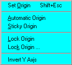
A number of options are provided to establish the Origin position, which is initially set to automatic, where the origin adjusts for each separate banding item.
Relative Origin from (Options)
- Name Lengths
Structure, Signal, Library and Silkscreen names have been extended up to 32 characters with no spaces or commas allowed. A much requested feature, only now made possible, providing greater flexibility when defining part names and description.
|
Vutrax 12.0 |
Previously |
|
|
Library Device Names |
32 |
12 |
|
Structure Names |
32 |
12 |
|
Silkscreen Names |
32 |
16 |
|
Required/Optional Pin Names |
32 |
12 |
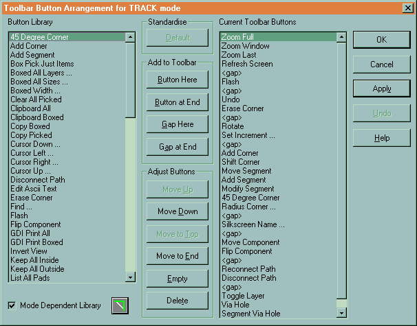
- Customisable Toolbars
Toolbar Editor from (Options)
The toolbar can be customised for each mode of operation. The current toolbar is defaulted but buttons can be moved, removed or added from the extensive Button Library (see dialogue below). Initially the buttons library is defaulted to the particular mode of operation, however by deselecting the box other buttons become available. The settings are subsequently stored in a .BTN file for each mode (Makelib.btn, Schem.btn, Sketch.btn and Track.btn).
- User Selectable Commands
You can customise your own sequence of commands and apply them to a menu entry or toolbar button. The menu system searches for a file USERCMDS.VTX that consists of a number of lines in the following format: -
<Command Number> <space> <Typed Command String>
e.g. Read Gerber RS274-X pad definition
10 READLIB GERB274X.LOG
This command can then be selected via: -
User Commands ... from (Options > User Commands)
To introduce this option into the Toolbar select the appropriate button (i.e. User Command 10) for the required mode.
- User Drawn Toolbar Buttons
This issue provides the ability to draw your own Toolbar buttons. Each button must be drawn as a bitmap image (.BMP) using Windows Paint or PaintShop Pro or similar. Please request Software Advice Notice 177 from the office or download it from our Web Site once the product is issued.
- More Colours
More colours are available via the use of palettes and a dialogue to set up display colours for pads and layers. Plus the ability to show SMD pads in different colours on opposite sides of the PCB. This dialogue can be invoked by either clicking on the layers/colour bar at the bottom of the screen or by selecting: -
Show Palette from (View)

- Pin Number Styles
A number of users requested extensions to pin number styles for large pin grid arrays and connectors with multiple rows not sequentially lettered.
|
Digits Only |
0 to 5225 pins |
|
Letters & Digits |
A to Z, AA to AZ, BA to BO, CC, DD, EE & FF, 0 to 71 |
|
Digits & Letters |
0 to 200, A to Z |
|
Letter/Symbol |
A to Z, + and – (no change) |
- Pad Shapes
By default pads will be displayed with their true drill hole sizes.
Specific Powerplane Thermal and Isolation pads can be defined specifically for any pad shape. When powerplanes is activated you have the choice as to whether these pad are used or ignored.
A Title can also be included for any pad definition. The name can be up to 32 characters (including embedded spaces).
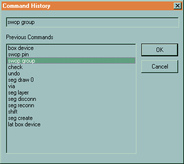
- Command Dialogue
By clicking on the command line area at the bottom of the screen invokes a command dialogue, which offers up to the last 32 commands executed. These can be selected, edited (if necessary) and actioned. This dialogue is also invoked, when you step back through the command history using function key – F3, after the 10th press or if it runs out of items.
- Automatic Saving
The automatic save scheme of Draft has been completely revised to operate by time rather than commands executed. The time intervals are determined by the AUTOSAVE keyword in CONFIG.MCH replacing WARNAFTER. By default the automatic saved feature operates after 15 minutes once the system has been idle for 5 seconds to a file DRAFT.SAV. All time and filename parameters are user definable.
- Macro Files (.DEX)
Generation of macro files allows for the inclusion of numerous controls for dialogue control, including titles, messages and buttons etc.
In addition a selection of macro files are provided for your convenience.
- Schematic Symbols
To make building schematic symbols easier, data points and silkscreen points can be in any order. More importantly the Library (device) name does not have to be the first in the list.
- Optimisation
Optimise now sets the final point of a signal to a non-zero width to simplify modification. This also prevents problems with powerplane signals marked as networked when using Optimise Edit and Optimise Plot.
Optimise Edit primarily for 3rd party routers and manually drawn artworks. Restores the artwork into an editable state.
Optimise Plot looks to rationalise the artwork by removing doubling of traces. Particularly useful when data is output to penplotters and aperture photoplotters.
- UTILITY ENHANCEMENTS -
Project, Directories and File Management
A complete revision has taken place to Project name and Directory/Folder handling. A single dialogue controls both aspects. Directory or folders can be created and searched for. Project names function in a similar way, however files that you generate are always positioned in the current project directory.
Installation and user names can now use ‘long file names’ including embedded spaces and dots. However to avoid compromising Vutrax internal naming conventions in schematics, we recommend that project names should not exceed 28 characters.
Comma Separated Listings
More and extended Comma separated lists including graphical import and export facilities are available which is especially useful to 3rd party software providers who may wish interface to and from Vutrax.
A new facility Vutrax to Comma generates the complete graphics as a comma separated list. Options are available to include analysis of Headers, Graphics or Constructions only.
There is also a decode facility, Comma to Vutrax, which interprets the data from a comma separated list to generate a standard Vutrax graphics file.
Gluespot has a newly introduced comma separated output.
Parts List comma list output has been updated to included supplier’s part numbers.
Rats Nest Generation
Building of Rats Nest Rules (.WRL) provides for Signal Aliasing. This feature allows FIXED pins and NCINP pins (generally for power rail names used in libraries) to be associated with a signal used on a schematic diagram, e.g. VCC to be synonymous with +5V.
It is often the case that the physical library definition for a component has its FIXED pins assigned to a name that you are not using on your schematic. The signal aliasing allows you to re-assign the fixed pin name.
Autoplace, Autotrak, Vuroute and Topdown Modify
All have explicit controls on the handling of Network Optimised signals. Options include Off, Normal Edit and Plot, similar to Draft.
Plot
- Gerber RS274-X Support
New control file GERB274X.HXY is provided for Gerber RS274-X format. This we suggest should become your default photoplotting output, and the menu reflects this for new installations.
It includes the automatic selection and definition of apertures, no need to worry about defining an aperture definition file .HNB for all those construction warnings. The apertures are embedded within each output file (.GBR – formally .GRB) so the manufacturer can interpret the data directly.
There are numerous Gerber Viewers commercially available, many of which can be downloaded from the World Wide Web (WWW) as either freeware or shareware. These viewers (if the capacity limits are not exceeded) allow you to view the apertures and Gerber data the RS274-X routine allocates. A special file is also generated, in addition to the .GBR files you make, GERB274X.GBR that contains the Gerber drawing commands necessary to illustrate the apertures as both flashed and drawn as appropriate.
For compatibility with Vutrax 11, control file GERBPHOT.HXY can still be used but coordinates will get rounded down. A new control file, GERB_T10.HXY, is however available which caters for the resolution of Vutrax 12.0 if you still prefer to control apertures yourself.
- Windows GDI Printers
Now supports the ‘I’ option to produce negative images directly to standard Windows printers.
Decode Gerber
Decode Gerber has been enhanced to recognise and ignore Gerber RS274-X macro sequences. As part of the Gerber 274-X output sequence, the aperture definition routine generates a number of files, two of which can be used directly with Decode Gerber. GERB274X.RNB the reverse aperture file, and GERB274X.LOG, which contains all the pad definitions for the resultant decoded file. This file should subsequently be merged with the resultant graphics file within Draft.
Default format for scaling is now n.4.
Vutrax to DXF
DXF output can output just one layer or a selected set of layers. You can also choose which apparent layer the 4 standard pad types appear on or whether they are suppressed. You can also choose that some layers have pads without tracks, useful for silkscreen output.
The FLAGS capacity limitation has been extended to 4095.
- SYSTEM ENHANCEMENTS -
System Menu
Tip of the Day has been introduced at start-up, to help discover those useful things you may have missed. These tips can be printed, individually or completely, turned off and restarted using: -
- Tips of the Day from (Help)
Text Printing
Text output to the printer now has additional controls for the quantity, whether odd, even or both pages should be printed and if copies are collated. Select
- Directives from (File > Text Print)
Vtxshell
An assortment of changes has taken place within the Vutrax Shell. Some specific changes are discussed below:
- Command History dialogue
The command history list and command line can display a dialogue for selection, cut, paste, and file browsing.
- Command Files
Command files (.BAT) can generate custom dialogue boxes for choice, text input, or file browsing. They can also change the Window Title and alter the Window State.
- Open Applications
New command OPEN finds the application associated with a supplied file, and attempts to display the document with it.
- Table
New filter command TABLE customises comma separated lists. SORT has field sorting capabilities.
See Text Editor
Files sizes of up to 8MB can be edited without overflowing to disk.
Selection of Read-only files through File dialogue.
Join Line (Ctrl+N) strips all but one space at the join so that joining indented lines is more powerful.
 For further Information, please e-mail us here
Computamation Systems Ltd.
Tel: +44 (0)1525 261 381
E-mail: sales@vutrax.co.uk
Vutrax is a registered trademark of Computamation Systems Ltd.