BULLETIN
Technical Support and the Latest Information for VUTRAX Users
Issue Number 31 |
April 2001 |
- Vutrax Version 12.3a-
Vutrax 12.3a is planned for release in May 2001 on the Windows Platform Windows 95, 98, ME, NT 3.51, NT 4.0, 2000.
Development for the first issue on Linux is proceeding in parallel and is expected 3Q2001.
The primary content of this bulletin is an outline of the enhancements. Operational details of the changes are embedded in the installed product.
Graphics files are interchangeable with Vutrax 12.0, 12.1 & 12.2. Other files are forward compatible, and in general backwards compatible if new features are not used.
- Availability -
When available, this issue of the software can be supplied from Downloads situated on our Web site (www.vutrax.co.uk) or on either CD-ROM or Floppy Disks.
Those who have subscribed to the Software Maintenance Agreement and require CD or Floppy media should return:
- The Configuration Disk
- Master & Interface Floppy Disks (if you have any - do not return the CD-ROM)
- A note of your media preference
Alternatively
- email us to request your Configuration file (via email).
'Download' customers will need to contact us to arrange for a configuration file.
'Freeware' customers can update from downloaded materials alone. The same 256 pin limits and indefinite use apply.
Users who have not subscribed to the Software Maintenance Agreement and would like to know more details of the costs involved, please telephone or e-mail the Computamation office on:
- 01525 261 381 -
- sales@vutrax.co.uk -
- Vutrax 12.3a Enhancements -
General
- Formal Support for Windows ME throughout.
- Changes to window selection in Windows 98, NT, 2000 and ME to stop windows popping up underneath unwanted windows.
Graphics Editor (Draft)
- Support for a new highlighting feature Blink Items from (Edit) to 'BLINK' any selection of items while viewing, moving the cursor, rubber banding etc. You can use this to highlight a signal you are working on, highlight power rails, etc. The setting mechanism includes all the methods also available for PICK, including by name, selected items, and individual segments and points.
Operations available for PICK are also available for BLINK, providing two distinct and independent selection arrangements. The existing 'Flash' scheme remains and is again distinct, though Flash and Blink do not occur together.
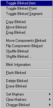
BLINK settings are preserved in the graphics file, though may not be maintained accurately by earlier issues.
- Moving groups of components (including mass-changing the orientations) that you have Blinked or Picked explicitly, by name, or by enclosing in one or more boxes.
- Selective 'Save As' based on items that are Boxed, Picked or Blinked, along with a related graphical Cut & Paste facility.
- The menus dynamically control 'Greying' of far more options to simplify selections. This has also allowed us to extend the local menus to include Boxed, Picked and Blinked operations.
- The Colours and Layers dialogue Show Palette from (View) includes controls for highlighting of Pick, Blink,
Pattern, Gluespots, Visible data points, enable/disable of the cursor grid, and whether drilled pads and VIAs
show their true hole size.
These features are also available through command line extensions (for example to alter your startup conditions). A command line extension allows initial colour settings from a user Palette file.
- New dialogues included for the Curve (curve?) command options - Curves, Fillets, and Spirals. Items enclosed in ( ) denotes typed commands:-
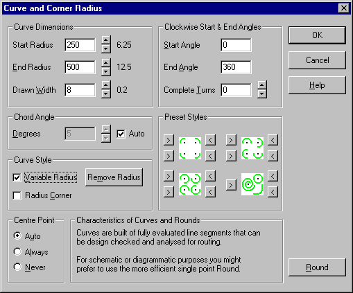
- Other new dialogues include,
- Dash Line (dash?) - Dashed lines, Dotted lines and Centre lines.
- Round (round?) - Schematic and other Curves & Ellipses
In addition ROUND offers a dialogue selection and new command line option to create a new point, rather than alter an existing one.
- GDI print schemes GDI Print Boxed and Clipboard Boxed from (File > Print Graphics) options include choice of having no heading, the current filename, or a user specified heading. You can also choose whether to include the date.
- A macro command (change signal and label.dex) is available to alter all Signals and Labels on a Schematic drawing from one name to another.
- When you alter the NAME of an already named item (Device, Signal etc.), existing Script, Data and Silk can, upon confirmation, be updated to match.
- Dimension from (Options) allows the selection of the decimal symbol, and optional 'thousands' separators. e.g. the continental style 12.345,67mm.
- Find from (Edit) dialogue can browse the content of existing Script Text, Data Points and/or Silk Legends when selecting items to search for. You can also search for particular round widths, and items with Blinked and/or Picked attributes.
- Capacity limited users can ask how much capacity is used, and can be warned when over a selectable percentage.
Design Rule Checking
- When Design Rule Checking and Emc Critic errors files are merged with an artwork, all deselected or 'Zilch' colour layers or pads are re-enabled, but user selected colours from the original artwork are preserved.
- Design Rules Checking includes two new checks:-
- Silkscreen Gap Rules (see dialog below) checks the interference between silkscreen inks and metal on
the side of the board on which it is printed, with various options for setting clearances, avoiding drilled centres
of VIA holes, etc.
Silkscreen Gap from (Tools > Routing > Design Check > Build Rules)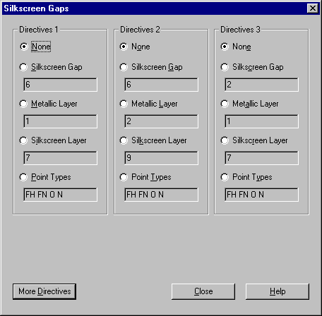
Point Types: Specifies the point types (FH, FO, FN, H, O, N, C, K, D, X, T) that the silkscreen is checked against. 'FO' (fixed drill holes) and 'O' (drilled vias) treat only the 'drilled centre hole' as something to avoid.
- Power Layers Rules (see dialog below) checks that every SMD (Fixed Node) pad connects to the specified
plane through a VIA (Hole) or drilled PTH component pad (Fixed Hole). This supplements the Split plane
checking features in EMCRITIC.
Power Layers from (Tools > Routing > Design Check > Build Rules)
- Silkscreen Gap Rules (see dialog below) checks the interference between silkscreen inks and metal on
the side of the board on which it is printed, with various options for setting clearances, avoiding drilled centres
of VIA holes, etc.
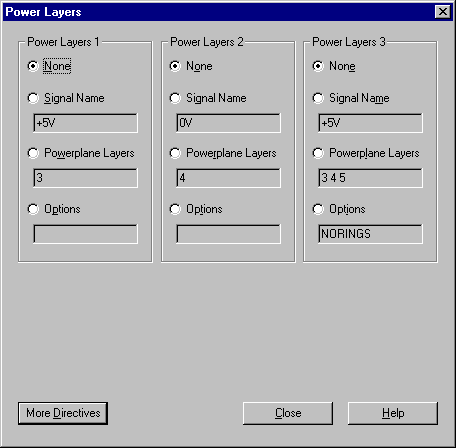
NORINGS suppresses checks that there is no isolation of Power signals to the powerplane (i.e. Broken ring or Nothing), and isolation for all other signals (Annular ring or Disk). Use this only if you check the artwork prior to Powerplane generation, or for special purposes.
Convert Pin List (Connect)
- Convert Pin List from (Tools > Interconnect) pin-to-pin list analyser has an option to process pin lists with an existing placement file (e.g. for top-down modification).
Users of the Pin-to-pin list input style sometimes need to revise the connection list for a partly or wholly completed layout. If you make the changes to the pin-to-pin file and re-analyse it you loose all of the placements you analysed unless you edit the connection (.WIR) files to remove all of the 'fresh' directives.
The new option signifies that the design already has an analysed placement file (.LAY), so initial Placement directives are omitted from the generated .WIR file. The device definitions have their silk references added to ensure they use the correct placement definition. When the rats-nest is generated the placement file must be included. Once you have the new rats nest you can merge the changes with the existing layout using Top-Down-Modify.
Parts List
- Parts List from (Tools > Postprocessing) output can now include information about the device included in the schematic library symbols which has been stored in the Schematic Index. Additional output options enable these features:-
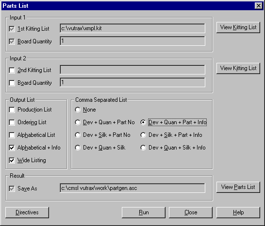
- The Alphabetical list of parts is included, with additional line(s) of information following the main entry for each part. To obtain this information an attempt is made to locate each device in the Schematic Index (Schemlib.Lix) and to extract the Index Information embedded in the schematic library. Index Information is an arbitrary line of up to 78 characters that can describe the device, but can include in-house part numbers and the like. Where a device is indexed more than once, non-identical entries produce multiple lines in the listing.
- The comma separated output forms is the same as above except that field 3 includes the index information. The item otherwise occupying field 3 is moved to field 4, and so on down the line. The Index Information is obtained as above, but multiple entries are separated on the same line using a semicolon (';') and a space. Fields which contain spaces or commas are quoted.
Alphabetical + Info
Dev + ...
Plot
- An additional Plot option Use Finished Size (Q2048)
CNC output, drill sizes etc. normally use the 'Drill Size' rather than 'Finished Size' for choosing drills, symbols etc. This option forces the 'Finished Size' to be used instead.
Customers who are not be involved with manufacturing details do not know the necessary increase in drill size to allow for through hole plating.
Using this option the CNC and other outputs can be based on the 'Finished' hole size instead, allowing the PCB fabricator to make the appropriate allowances themselves.
Warning - NC Drill Definition files (.NNB)and Drill Pattern size list MUST include the actual Finished Drill Size.
Vutrax Shell
- Includes features for processing lists of files, including searching subdirectories and generating true numeric sequences.
- Support for command files carried backwards and forwards between Linux and Windows.
- New SORT option to handle quoted fields in comma separated lists.
- New TABLE option to re-arrange the columns in comma separated lists.
- New TYPE options to paginate and wrap output to fit Personal Organisers.
See Text Editor
- Options to handle files in both Linux and Windows conventions, including both automatic selection and forcing required styles. (Existing utility VTXUDDU handles mass conversion).
- Highlighting of the various new keywords in Rules files.
- Clarification of the confirmation and error messages for Copy and Cut.
- 'Cut' and 'Copy' to file include the names in the Recent Files list to make them easier to 'Paste'.
Windows Bitmap to Vutrax Format Converter
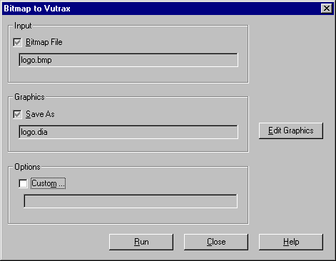
- This free Interface Module for converting bitmaps to Vutrax format can now be used through the menu system.
- The Bitmap to Vutrax converter handles more variations of monochrome bitmap, and long file names.
Toolbox
- DXFTOVTX supports AutoCAD layer numbers up to 255.
Computamation Systems Ltd.
Tel: +44 (0)1525 261 381
e-mail: sales@vutrax.co.uk
Vutrax is a registered trademark of Computamation Systems Ltd.
