BULLETIN
Technical Support and the Latest Information for
VUTRAX Users
|
Issue Number 32 |
August 2002 |
- Vutrax Version 12.4a -
Vutrax 12.4a is planned for release in September 2002 for Windows 95, 98, ME, NT 3.51, NT 4.0, 2000, XP, and Linux operating systems.
The primary content of this bulletin is an outline of the enhancements. Operational details of the changes are embedded in the installed product.
Graphics files are interchangeable with Vutrax 12.0, 12.1, 12.2 & 12.3. Other files are forward compatible, and in general backwards compatible, new features are preserved but ignored.
- Availability -
When available, this issue of the software can be supplied from Downloads situated on our Web site (www.vutrax.co.uk) or supplied on a CD-ROM.
Those who have subscribed
to the Support and Update
Rights Agreement and require a
CDROM should return:
The Configuration Disk
Alternatively:
email us to request your Configuration file (via email).
'Download' customers will need to contact us to
arrange for a configuration file.
'Freeware' customers can update from downloaded materials
alone. The same 256 pin
limits and indefinite use
apply.
Users who have NOT subscribed to 'Support and Update Rights' and would like to know more details of the costs involved, please telephone or e-mail the Computamation office on:
- 01525 261 381 -
- sales@vutrax.co.uk -
- Vutrax 12.4a Enhancements -
General
- Interactive facilities that
generate 'backup' files now append the .bak extension
to the current extension, keeping different
backup files for different jobs distinct.
- The
Automatic Saving features have
been enhanced to include much more control of the name
used by DRAFT, and
enable/disable and internal specification for the SEE Text
Editor. Both DRAFT and the SEE Text Editor default
to name:-
<ORIGINAL NAME>.auto.bak
- On-line HELP and Tutorials now includes selection to format the output for printing, and, depending on the volume, print one or more of just one page, the whole section, or the whole volume. This is particularly useful when working through the tutorials.
Draft Interactive Graphics Editor
- The
'OPTIMISE' feature has been
substantially extended to include
sequencing and rationalisation of arbitrarily drawn
structures, and to include optimisation of a specific
signal by name or explicit selection, rather than signas
with just
optimisation markers set.
Warning: Some previously available typed commands have changed :-
OPT
becomes
OPT MARKER
or
OPT M
OPT EDIT
becomes
OPT EDIT *
or
OPT E *
OPT PLOT
becomes
OPT PLOT *
or
OPT P *
Two forms of optimisation are available:-
'Network' optimisation is the connecting of tracks between PCB component pads to the nearest neighbour. A set of markers per signal knows whether the signal has been changed and might benefit from optimisation, and whether 'Network' optimisation is allowed.
'Sequence' Optimisation is the adjusting of the drawing sequence of non-PCB tracks to make the count sequences of drawn segments sequential. (This feature is new in Vutrax 12.4)
- 3 additional commands now set the
'Optimise Required' marker on the selected signal:-
Erase Route from (Edit > Erase)
Disconnect Path from (Reconnect)
Reconnect Path from (Reconnect)
- Track Length and Impedance measurements has been extensively revised
to include partial tracks, and comparison of
whole or partial tracks to enable trace lengths matching
in time critical designs.
Routed sections of track can be 'Picked' and/or 'Blinked', then compared against a selected route or compare the 'picked' section with the 'blinked' section or vice versa. This can be useful where signal traces must be matched length and/or resistance.
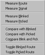
- 'PICK'
and 'BLINK' setting options now include picking
Signal Routes, sequencing between zero widths
(including curve
fillets) and an explicit range of points.
- Script
points in suitable protected structure, such as part names in
schematic symbols, can be updated and/or moved
with a simple confirmation, rather than changing modes.
- Draft now assumed Schematic (SCHEM) mode when started on a new file.
- The parameters dialogue box after
selecting Browse has been changed to automatically select
Always Browse so that
the image will not need repainting next time you want
to browse. If you explicitly cancel this setting, it is
not automatically
invoked again during the session.
- The BREAK command on a
named structure can opt to apply the original name, or leave
them un-named to one or more
of the fragments.
- 'BANDING' control can be used to provide your own prompt
when you create your own function key or toolbar buttons
-
Band Title.
- New command options, 'OUTLINE' is
introduced to provide explicit control of outline drawing
direction, and to show the
effect of milling a particular set of cut-outs and
profiles. The new Plot Milling
outputs (see below) are
generally intended to
use the automatic sequencing and direction settings.
However, complex requirements require the user to draw
outlines in
the required order, hence the OUTLINE command provides
schemes for determining current outline order and to
adjust it.
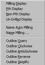
- Draft can now determine which pads are plated or non-plated through the pad definition, by the presence/absence of the keyword CNCNONPTH and also CNCMILL which can be used for large holes that require milling as opposed to NC Drilling. Using
Pth Display from (Options > Milling)
Non-Pth Display from (Options > Milling)
Un-Drilled Display from (Options > Milling)
- The
'GROUNDPLANE' facility now
identifies separately generated sections of groundplane by
naming the outline and fill to
identify the signal name,
layer and a sequence count of
separately generated areas for each signal and layer. The name takes the form:-
GROUNDPLANE_<SIGNAL NAME> _L<LAYER>#<COUNT>
Also removing groundplanes has an equivalent selection feature, a multiple selection box for you to choose which you want removed. Useful if you want to remove groundplanes from a particular layer or for a particular signal.
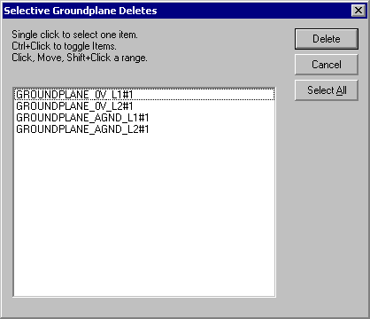
Also Groundplane automatically sequences the outlines structure to fill.
Design Management
- Any structure with one or more Component Pads is checked to ensure that none of the Pads or VIAs include either CNCMILL or CNCNONPTH in any of the pad shape definitions.
- Structures named CNCMILL that
include component pads.
Design Rule Checking
Includes logical checks that connectivity is not assumed though holes designated Non-PTH, and that milling objects are not confused with signals.
Forward Modify
Checks that the SIDE layer settings are compatible between the Original Artwork and the New Rats Nest.
EMCritic and Powerplane
Automatically sequence region outlines.
Analyse Placement and Back Modify
Includes in the .LAY file details of the position, size, orientation and content of Script text found in the Component silkscreen outline, thus these script points can be preserved throughout a new layout. These are normally applied when a new silk screen is generated using this layout file.
Rats Nest (Wire)
If the Layout file (.LAY) contains information on how Script text points in the Silkscreen boxes has been altered then these changes are applied as the new silk screen is generated.
Any 'value' script (designated by containing '#' in the library symbol) is still normally assigned the device value, ignoring any different string in the layout file (.LAY). Changes to position, size and orientation are preserved. If Script points are added to a PCB silk screen then they should be added at the end of the silk screen structure.
Two additional Extra Options are available in the 'suppress' group box:-
Script Update (-YC) - This option completely suppresses the script update feature. Rats Nest (Wire) works as in Vutrax 12.3b
Value Update (-YV) - When the script update feature is active, this option preserve the 'value' text from the layout file, rather than assigning the value to match the net list/schematic.
Utility
- Now selects between Edit and View-only mode when changing files or opening an extra window.
- Provides a means of obtaining and manipulating the time stamp of a file from within command files.
- Command 'TOUCH' can be used to alter the time stamp(s) of files.
- Command 'FC' has improved options for skipping whitespace and indents.
- Command has arithmetic calculation
capabilities for both integer and floating point.
- PRINTFRM detects when the direct printer output options
specified are incompatibly with the operating system,
and modifies them.
- The [Search] for files
feature now writes the result to a file as well.
See Text Editor
Vtxshell
Text Printing
Search
Manufacturing
Plot
- New Plot facility MILLING which can directly generate CNC output for Routing (board cutting) machines. Milling can be used for creating slots and pierced areas within a PCB, and for cutting the outer profile(s) of the finished board or panel of boards.
Plot expects these new file extensions for MILLING files:-
.mxy
The Plot Control File format specification.
.mnb
The 'Milling definition file 'nib' defining the cutters.
The artwork must be prepared in such a way that an outline structure(s) are named CNCMILL<PRIORITY>, where <PRIORITY> (optional) is usually a number e.g. CNCMILL1 which determines the order of the milling sequence. Also large holes that require milling as opposed to NC Drilling can be named CNCMILL in the Pad Definition. The new Draft Outline facility (see above) can be used to determine the direction of the cutter and display, Blinking or Picked, the cut-out and profile structures.Also 'mill_to_vutrax.mxy' can be used to create a Draft viewable milling sequence. If you use mill_to_vutrax.mnb you will see a simple 'stick diagram'. Using a 'real' .mnb tool specifications you will see the actual strokes.
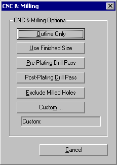
- Plot can generate CNC drill
data or drill charts sensitive
to Plated-through (drilled prior to plating) from holes
that must
NOT be plated through (drilled
after plating, often along with profile milling). By
default holes are expected to be plated
through. Every Fixed Hole
(FH) and Hole (H) in the artwork
is examined to see whether the Pad shape
definition 'Name'
field starts CNCNONPTH, or a referenced pad needed to plot be
plotted on one of the specified layers is also
named.
- Photoplotting using Gerber 274X
changes the orientation of
thermal rings to match the graphics display, and provides
and option to choose your own orientation. By default
the orientation is now set to 45 degrees.
- Plot standard control files now introduce no plot offset for any of CNC
Drilling, Gerber Photoplotting or
CNC Milling.
Mixing and matching numeric control sequences produces
registered results.
Toolbox
- New facility 'PANELIZE' provides a
facility for automating the production of 'panels' of a
given artwork on larger production
PCB blanks.
Panelize from (Tools > Postprocessing)
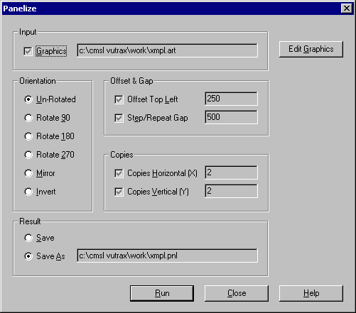
Artwork size determination includes all layers, and the physical size of artwork elements. If the drawing board size limits are exceeded there is a warning which includes the first erroring coordinate, but you are allowed to continue. The Menu system assumes a new file extension .PNL for 'panelized' artworks.
Warning: The panelized form is a manufacturing output. The original artwork should be preserved for use in modification cycles.
Computamation Systems
Ltd.
Tel: +44 (0)1525 261 381
e-mail:
sales@vutrax.co.uk
Vutrax is a registered trademark of Computamation Systems Ltd.
